Introduction
아래의 Design Guide for MIG IP (1/3)을 보고 난 후, 지금 보고있는 BLOG를 보아 주세요.
Design Guide for MIG IP (1/3)
Introduction Xilinx MIG (Memory Interface Generator) IP를 생성할 경우 User Logic과 연결되는 Interface는 두 가지가 있습니다. Standard User Interface AXI4 Interface 여기서는 Standard User Intrface..
740280.tistory.com
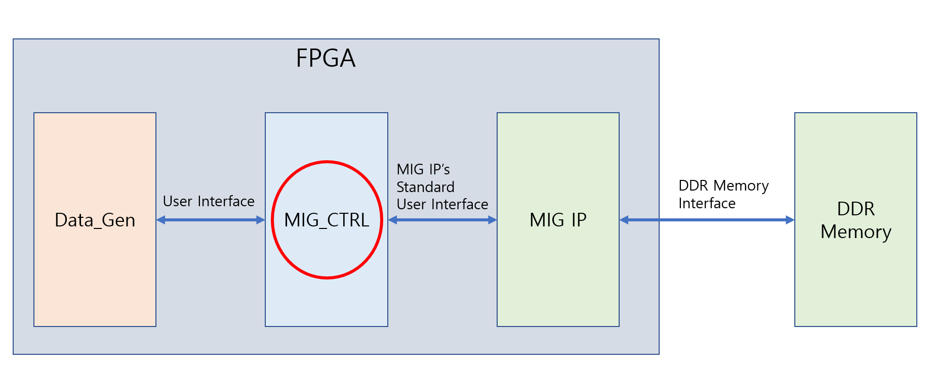
여기서는 MIG IP를 Control하기 위한 MIG_CTRL ( mig_ctrl.vhd )를 design함에 있어 FSM ( Finite State Machine )을 이용하여 어떻게 구현하는지 설명하겠습니다.

PC 사용환경은 다음과 같습니다.
- OS : Windows 10 pro ( version : 20H2 )
- Vivado version : 2020.2
FSM ( Finite State Machine ) for MIG IP
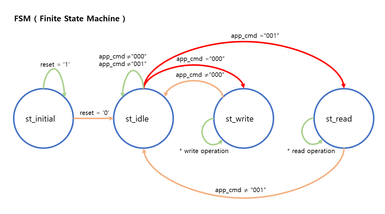
아래의 FSM ( Finite State Machine ) diagram과
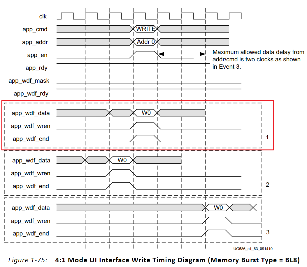
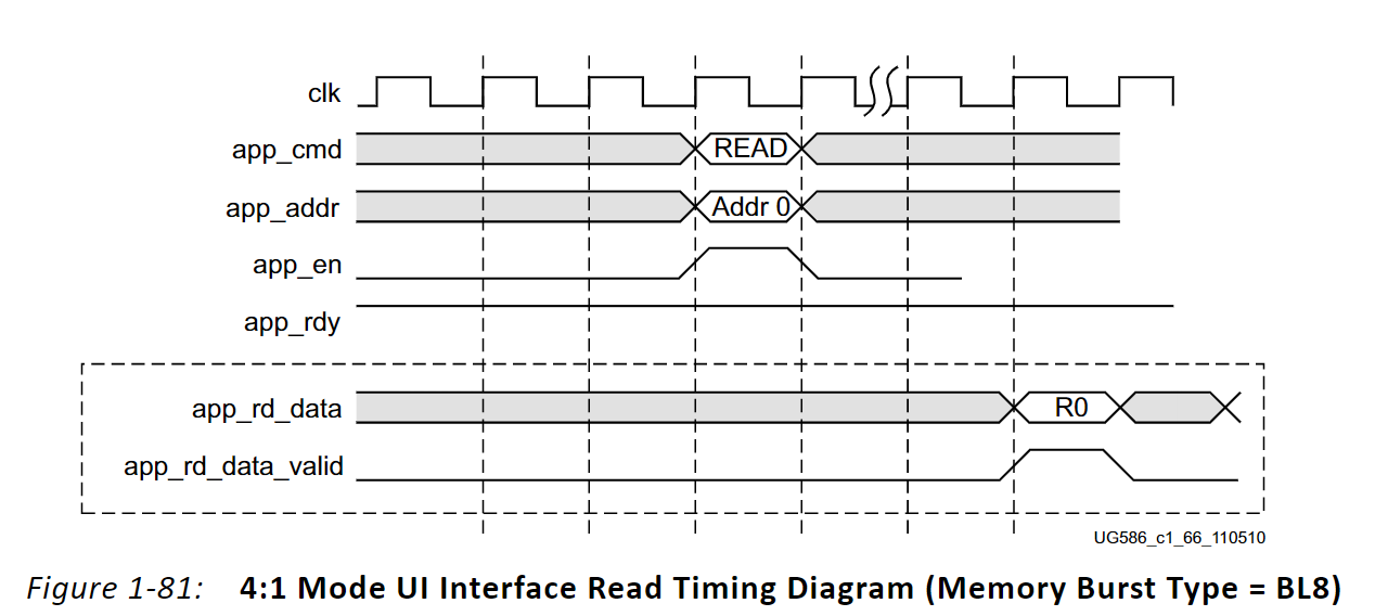
1,2,3 중에서 1번 Write Timing Diagram 그리고 Read Timing Diagram을 눈여겨 보아 주세요.


위에 있는
FSM ( Finite State Machine ) diagram과
1,2,3 중에서 1번 Write Timing Diagram 그리고 Read Timing Diagram
이렇게 세가지를 기준으로 Code를 구현하면 다음과 같습니다.
MIG IP's Standard User Interface pin과 연결되는 부분과 개발자의 code와 연결되는 User Interface pin 정의는 다음과 같습니다. |
entity mig_ctrl is port ( --========================================================== --=============== MIG IP's Standard USER Interface =================== --========================================================== ui_clk : in std_logic; ui_clk_sync_rst : in std_logic; init_calib_complete : in std_logic; app_cmd : in std_logic_vector( 2 downto 0) ; app_rdy : in std_logic; app_en : out std_logic; app_addr : out std_logic_vector( 27 downto 0) ; app_wdf_rdy : in std_logic; app_wdf_wren : out std_logic; app_wdf_data : out std_logic_vector(127 downto 0); app_wdf_end : out std_logic; app_rd_data_valid : in std_logic; app_rd_data : in std_logic_vector(127 downto 0) ; app_rd_data_end : in std_logic; --========================================================== --=============== USER Interface =========================== --========================================================== state : out std_logic_vector( 3 downto 0); write_rdy : out std_logic; write_en : in std_logic; write_addr : in std_logic_vector( 27 downto 0); write_data : in std_logic_vector(127 downto 0); read_rdy : out std_logic; read_en : in std_logic; read_addr : in std_logic_vector( 27 downto 0); read_valid : out std_logic; read_data : out std_logic_vector(127 downto 0); reset : out std_logic ); end mig_ctrl; |
아래의 code는 4개의 state에 대한 정의를 합니다. ( st_initial, st_idle, st_write, st_read ) |
signal state current_state : std_logic_vector( 1 downto 0) ; signal next_state : std_logic_vector( 1 downto 0) ; constant st_initial : std_logic_vector( 1 downto 0):= "0001" ; constant st_idle : std_logic_vector( 1 downto 0):= "0010" ; constant st_write : std_logic_vector( 1 downto 0):= "0100" ; constant st_read : std_logic_vector( 1 downto 0):= "1000" ; |
아래의 code는 각 state가 "app_cmd"의 value에 따라 어떤 state로 이동하는지 구현한 부분입니다. 위에 있는 FSM ( Finite State Machine ) diagram과 비교하여 보세요. |
state_decode: process ( current_state, app_cmd ) begin case ( current_state ) is when st_initial => next_state <= st_idle; when st_idle => if ( app_cmd = "000" ) then next_state <= st_write; elsif ( app_cmd = "001" ) then next_state <= st_read; else next_state <= st_initial; end if; when st_write => if ( app_cmd = "000" ) then next_state <= st_write; else next_state <= st_idle; end if; when st_read => if ( app_cmd = "001" ) then next_state <= st_read; else next_state <= st_idle; end if; when others => next_state <= st_initial; end case; end process; |
아래의 code는 각 state에서 입력 조건에 따라 어떤 동작을 하는지 구현한 부분입니다. 1번 Write Timing Diagram 그리고 Read Timing Diagram과 비교하여 보세요. 앞으로 개발자가 구현하여야 할 부분은 : (1) Write 동작의 경우, write_en을 '1'로 놓고 ( write_rdy = '1' )의 조건에서 write_addr와 write_data를 입력하면 됩니다. (2) Read 동작의 경우는 read_en을 '1'로 놓고 ( read_rdy = '1' )의 조건에서 read_addr를 입력하면 됩니다. 이 후, read_valid가 '1'가 되면서 원하는 read_data의 출력을 확인할 수 있게 됩니다. 이 부분은 다음 블로그( Design Guide for MIG IP (3/3) )에서 다루어 보겠습니다. |
comb_decode: process ( current_state, app_rdy, app_wdf_rdy, write_addr, write_addr, read_addr) begin case ( current_state ) is when st_initial => app_en <= '0'; app_addr <= x"0000000"; app_wdf_wren <= '0'; app_wdf_end <= '0'; app_wdf_data <= (others => '0'); when st_idle => app_en <= '0'; app_addr <= x"0000000"; app_wdf_wren <= '0'; app_wdf_end <= '0'; app_wdf_data <= (others => '0'); when st_write => if ( app_rdy = '1' and app_wdf_rdy = '1' ) then --( Write 동작 ) app_en <=write_en; app_addr <= write_addr; app_wdf_wren <= write_en; app_wdf_end <= write_en; app_wdf_data <= write_data; else app_en <= '0'; app_addr <= write_addr; app_wdf_wren <= '0'; app_wdf_end <= '0'; app_wdf_data <= write_data; end if; when st_read => if ( app_rdy = '1' ) then --( Read 동작 ) app_en <= read_en; app_addr <= read_addr; app_wdf_wren <= '0'; app_wdf_end <= '0'; app_wdf_data <= ( others => '0' ); elsif ( app_rdy = '0' ) then app_en <= '0'; app_addr <= read_addr; app_wdf_wren <= '0'; app_wdf_end <= '0'; app_wdf_data <= ( others => '0' ); end if; when others => app_en <= '0'; app_addr <= x"0000000"; app_wdf_wren <= '0'; app_wdf_end <= '0'; app_wdf_data <= ( others => '0' ); end case; end process; reset <= ui_clk_sync_rst and init_calib_complete; rst <= ui_clk_sync_rst and init_calib_complete; write_rdy <= app_rdy and app_wdf_rdy; read_rdy <= app_rdy; write_addr_data: process ( ui_clk, rst ) begin if ( rst = '1') then read_valid <= '0'; read_data <= x"00000000000000000000000000000000"; elsif ( ui_clk'event and ui_clk = '1' ) then read_valid <= app_rd_data_valid; read_data <= app_rd_data; end if; end process; |
아래의 code는 매 clock cycle마다 현재 state에서 다음 state로 이동함을 구현한 부분입니다. |
state_seq: process ( ui_clk, rst ) begin if ( rst = '1') then current_state <= st_initial; state <= st_initial; --(현재 state를 출력으로 보내기 위한 code입니다) elsif ( ui_clk'event and ui_clk = '1' ) then current_state <= next_state; state <= next_state; --(현재 state를 출력으로 보내기 위한 code입니다) end if; end process; |
위 source code를 보면 FSM ( Finite State Machine ) diagram을 그림으로 구현한 후에 설계를 하면 보다 쉽게 구현할 수 있음을 알 수 있습니다.
지금까지 MIG IP를 Control하기 위한 FSM ( Finite State Machine )을 어떻게 구현하는지에 대하여 알아보았습니다.
다음은 아래 링크의 블로그를 통하여 위에서 언급한 "앞으로 개발자가 구현하여야 할 부분"인 실제 Data 생성 code를 위 source code와 연결하여 MIG IP를 통해 DDR memory에 Write한 Data와 Read한 Data가 동일한지를 살펴보겠습니다.
Design Guide for MIG IP (3/3)
Introduction 만일 Design Guide for MIG IP (1/3)과 Design Guide for MIG IP (2/3)의 내용을 보지 않았다면.... 아래의 Design Guide for MIG IP (1/3)과 Design Guide for MIG IP (2/3)을 보고 난 후에..
740280.tistory.com
여러분의 FPGA 설계에 조금이라도 도움이 되었으면 합니다.
오늘도 좋은 하루 되세요.
(공감, 구독, 댓글은 저에게 힘이 됩니다!)
Create Date: February 04, 2021
Posted By: Mouessee
Xilinx 본사는 한국 내에 Corporate and Sales Distributor로 MAKUS를 두고 있습니다.
Xilinx 국내 Corporate and Sales Distributor인 MAKUS는 XIlinx FPGA Device를 기술영업을 통해 판매하며 기술지원이 가능합니다.
MAKUS www.makus.co.kr
관련 BLOG
Design Guide for MIG IP (1/3)
Introduction Xilinx MIG (Memory Interface Generator) IP를 생성할 경우 User Logic과 연결되는 Interface는 두 가지가 있습니다. Standard User Interface AXI4 Interface 여기서는 Standard User Intrface..
740280.tistory.com
Design Guide for MIG IP (3/3)
Introduction 만일 Design Guide for MIG IP (1/3)과 Design Guide for MIG IP (2/3)의 내용을 보지 않았다면.... 아래의 Design Guide for MIG IP (1/3)과 Design Guide for MIG IP (2/3)을 보고 난 후에..
740280.tistory.com
'Xilinx > IPs' 카테고리의 다른 글
| How to create Xilinx MIG IP for Custom Part (0) | 2022.06.23 |
|---|---|
| MIG IP에서 사용되는 3 종류의 Clock에 대하여 (0) | 2022.05.18 |
| DisplayPort에 대한 Xilinx Solution (0) | 2022.05.16 |
| Design Guide for MIG IP (3/3) (1) | 2022.05.16 |
| Design Guide for MIG IP (1/3) (0) | 2022.05.16 |